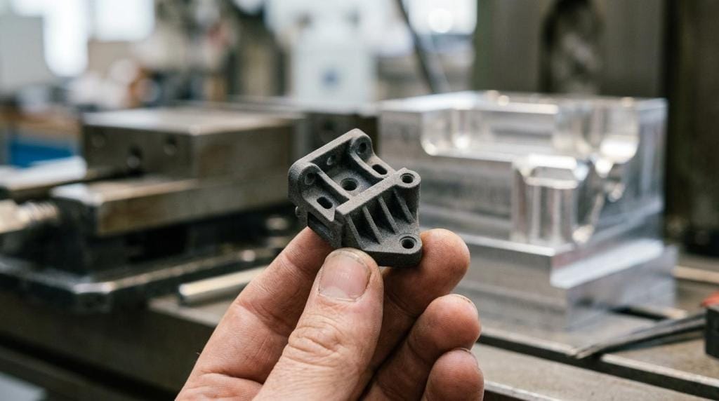
Product development prototypes turn assumptions into evidence. They help teams reduce technical risk, avoid late design changes, and move from concept to manufacturable part with fewer costly surprises. The core problem they solve is uncertainty: whether a product will fit, function, survive use, satisfy users, and make sense to produce. When prototypes are chosen with discipline, they shorten decision cycles instead of adding extra work.
What is a product development prototype?
A product development prototype is a test article built to answer a defined design question. MIT and IDEO both frame prototypes as learning tools, not mini production runs, which is why they reduce uncertainty around fit, function, usability, and manufacturability.
A prototype can be physical, digital, or both. In practice, most teams use a stack of prototype types across the program: sketches and foam models early, CAD and simulation in the middle, then printed or machined parts for engineering validation.
The strongest teams avoid treating all prototypes the same. A cardboard mock-up for ergonomics, an SLA model for appearance, and a CNC aluminium bracket for load testing each have a different job. If the purpose is unclear, the prototype usually fails even if the part looks impressive.
Which prototype question should you answer first?
The first prototype should answer one question, not ten. IDEO and NIST both support early testing around a single uncertainty, because focused prototypes produce faster decisions and cleaner design changes.
Step 1: Define the highest-risk unknown
Start with the issue most likely to delay the project. That might be hand feel, assembly clearance, sealing, stiffness, thermal exposure, or user workflow. If a design fails on that point, then any time spent polishing appearance is misplaced.
Step 2: Match the prototype to the question
If you need to test ergonomics, a rough foam or printed shell is enough. If you need thread engagement or load paths, then a machined or engineering-grade printed part is the better evidence. A common mistake is asking a visual model to prove mechanical performance.
Step 3: Set a pass or fail rule before building
Write the test condition before the file goes to manufacture. That could be a tolerance band, force threshold, temperature range, or assembly time. Pro tip: if the team cannot agree on success criteria, it is too early to order the part.
What prototype development companies are the best fit for industrial teams?
The best prototype partner depends on risk, speed, and material needs. PartMade3D, Protolabs, and Hubs are useful benchmarks because they represent different mixes of industrial additive manufacturing, rapid quoting, and broad prototyping access.
For engineering and procurement teams, the useful question is not “who is biggest?” It is “who can supply the right evidence fastest?” A strong partner should support design intent, realistic materials, and revision cycles without pushing the wrong process.
- PartMade3D: A strong fit for industrial teams needing production-minded additive manufacturing, fast quoting, and access to materials like PA12-CF, ASA, TPU, ESD-safe, and heat-resistant polymers. The value is especially clear when Australian teams need local support, quick turnaround, and a path from prototype to tooling or end-use parts.
- Protolabs: A well-known benchmark when teams need rapid access to CNC, moulding, and additive options with strong design-for-manufacture feedback.
- Hubs: Useful when sourcing flexibility matters and a team wants broad manufacturing network access across prototype methods.
- Stratasys Direct: Relevant as a benchmark for larger industrial additive and production support requirements, especially where process breadth matters.
How do you choose between 3D printing and CNC machining for prototypes?
3D printing is usually faster for early geometry, while CNC machining is stronger for production-like behaviour. Hubs and Protolabs both position the choice around setup time, tolerances, material realism, geometry freedom, and part quantity.
Choose 3D printing when shape complexity matters more than exact production behaviour. Internal channels, lattice structures, complex ducts, and one-off housings are often quicker and cheaper to print because there is little setup and no tooling. SLS nylon and industrial FDM are especially useful for rugged functional prototypes.
Choose CNC when the prototype must behave much closer to the final part. Aluminium, acetal, stainless steel, and engineering plastics provide better confidence for threaded features, mating faces, load-bearing parts, and tolerance-sensitive assemblies.
The trade-off is simple. If geometry is hard and the learning goal is early, additive usually wins. If material fidelity and tight surfaces drive the decision, CNC usually wins. A common misconception is that a strong printed polymer always replaces machined engineering plastic. It often does not.
What are the best prototype materials for function, fit, and appearance?
PA12, ABS-like resins, and aluminium solve different prototype questions. Formlabs, EOS, and Stratasys material libraries consistently show that the best material depends on whether you need appearance, repeated handling, heat resistance, or mechanical evidence.
Material choice affects what the prototype can prove. PLA may be fine for a display shell, but it is a poor basis for under-bonnet evaluation. Standard SLA resin can look excellent, yet may crack under repeated clips or impact. PA12 is widely used because it balances toughness, wear resistance, and functional realism, while aluminium remains the safer choice for high-load or threaded validation.
A useful rule is to match the material to the failure mode you are trying to expose.
- Appearance models: SLA resin or fine-detail polymer for surface finish, branding review, and investor demos
- Fit and assembly checks: ABS-like materials, PA12, or machined plastic for snap fits, interfaces, and clearance testing
- Rugged functional tests: PA12, carbon-filled nylon, or aluminium where repeated handling and structural behaviour matter
- Heat or chemical exposure: ASA, heat-resistant polymers, or metals when the part faces UV, elevated temperature, or fluids
- Flexible features: TPU or elastomer-like materials for seals, grips, strain relief, and compression behaviour
How should you move from concept model to functional prototype?
The fastest route is staged fidelity with deliberate checkpoints. ISO 9001 design controls and common hardware SOPs both support gradual verification, because each stage should remove a specific category of risk before the next spend.
Step 1: Start with low-cost concept proof
Use sketches, foam, cardboard, or coarse 3D prints to test scale, layout, reach, and installation space. This stage is about rejecting bad ideas quickly, not perfecting details.
Step 2: Build a fit and form prototype
Move into CAD-driven parts with enough accuracy to assess interfaces. This is where printed housings, brackets, and enclosures become useful. If assembly clashes appear here, then redesign before ordering higher-value parts.
Step 3: Build a functional prototype in a realistic material
Use PA12, filled polymers, aluminium, or stainless steel once the questions shift to durability, fastening, temperature, or repeatability. Pro tip: do not jump to this stage because stakeholders want a polished sample. High fidelity too early can lock in avoidable cost.
Is low-fidelity or high-fidelity prototyping better at each stage?
Low-fidelity is better early, and high-fidelity is better late. MIT and IDEO both treat fidelity as a tool for timing, because the wrong fidelity at the wrong stage either hides risk or wastes budget.
Low-fidelity prototypes are fast and disposable. They invite feedback, which is exactly what you want when architecture, ergonomics, or workflow is still fluid. Teams often produce several rough concepts in days, then narrow the field before any expensive fabrication begins.
High-fidelity prototypes are valuable when the design question needs realistic geometry, tolerances, or material behaviour. They support design verification, stakeholder approval, and pre-production planning.
The trade-off is psychological as well as technical. Rough prototypes invite criticism. Polished ones often shut it down. A common mistake is treating a premium-looking prototype as proof of product readiness. If the internal evidence is weak, surface finish changes nothing.
A practical cadence is to run rough iterations in days to two weeks, then 2 to 4 medium-fidelity cycles, then 1 to 3 high-fidelity rounds for final validation.
How do you validate a prototype before the next design revision?
Validation should be planned before the part is built. ISO 9001 and ISO 14971 both point teams toward documented verification logic, because test results only help when they connect clearly to design decisions.
Step 1: Write the test plan first
Define the load case, user task, environment, and acceptance criteria. That might include torque, cycle count, thermal range, ingress risk, or assembly time. If the part passes, what will you do next? If it fails, what changes will follow?
Step 2: Test the prototype in realistic conditions
Bench tests are useful, but field conditions often reveal the real problem. A robotics gripper, mining bracket, or medical fixture should be evaluated in the nearest practical use environment. Pro tip: videos and photos of failures are often more useful than pass notes alone.
Step 3: Capture revision-ready findings
Translate the outcome into CAD edits, tolerance changes, material updates, or process changes. A frequent misconception is that prototype testing ends with “works” or “doesn’t work”. Good validation produces a controlled list of what changes, what stays, and what still needs proof.
Which standards and controls matter for prototype development?
ISO 9001, ISO 10303 STEP, and ISO/ASTM 52920 matter because prototypes sit inside controlled design and manufacturing workflows. In regulated fields, ISO 13485 and ISO 14971 add design control and risk management from concept through verification.
Standards do not tell you which prototype to print tomorrow. They do something more useful: they make sure design inputs, outputs, changes, risks, and validation records stay connected. That matters when a prototype drives a critical decision, especially in aerospace, defence, medical, and industrial equipment programs.
For most teams, the practical standard stack looks like this:
- ISO 9001: Design and development controls, review points, change management, and traceable verification
- ISO 10303 STEP: Reliable CAD data exchange between systems, suppliers, and downstream manufacturing
- ISO/ASTM 52900 and 52920: Common additive manufacturing terminology, qualification principles, and quality assurance logic
- ISO 13485: Medical device quality system requirements where prototypes feed formal design controls
- ISO 14971: Risk management for medical products, including hazard identification and control effectiveness
How does rapid prototyping reduce development time and risk?
Rapid prototyping shortens the loop between CAD and evidence. NASA and ORNL case material shows why it matters: faster iteration cuts downstream rework, lowers scrap risk, and improves design decisions before production tooling is committed.
The gain comes from cycle time. A team can model, build, test, revise, and repeat before expensive process commitments are made. If a printed duct exposes an airflow issue in week two, then the program avoids discovering it after mould tools or production fixtures are ordered.
This approach also improves communication. Engineers, buyers, maintenance teams, and operators usually make better decisions with a part in hand than with a drawing alone.
The trade-off is that speed does not replace judgement. If a rapid prototype uses the wrong material or test method, then it can create false confidence just as quickly. That is why industrial services with engineering input, fast quoting, and material guidance are often more valuable than raw print speed alone.