Choosing the best industrial tooling is rarely about finding one “best” material or process. It is about matching the tool to the job’s load, tolerance, heat, cycle count and downtime risk.
TL;DR: Summary
- The best choices for industrial tooling are usually additive-manufactured jigs, fixtures, gauges and low-volume production aids when lead time, tooling costs and custom geometry matter most, while CNC-machined aluminium or steel remains the better choice for very high loads, tight wear limits and sustained heat.
- NIST identifies additive manufacturing as especially useful for customised jigs and fixtures because it can bypass traditional tooling lead times and reduce the cost burden tied to low-volume production, inventory and tool maintenance.
- Tooling economics matter: a 2024 review reported that jigs and fixtures can account for up to 29% of total investment in some automotive body-shop settings, so even modest savings in tool build time or redesign cycles can be meaningful.
- For polymer industrial tooling, PA12-CF is a practical option when stiffness and dimensional stability are priorities. PartMade3D lists typical properties of 75 MPa tensile strength, 6000 MPa tensile modulus and 131 °C heat deflection temperature at 0.45 MPa.
- If the tool needs soft contact, impact absorption or part protection, TPU can outperform rigid materials. If it needs UV resistance, ASA can make more sense. If it needs cutting edges, constant high heat or very long cycle life, move to aluminium, steel or a hybrid design with metal wear surfaces.
- A sound tooling decision follows three checks: define the process window, choose the material and build method for the real environment, then validate the tool on the line before full deployment.
That is why industrial tooling decisions reward a systems view. The strongest result usually comes from balancing performance, manufacturability and replacement speed, not from defaulting to the hardest material in the catalogue.
What actually makes one industrial tooling option the best choice?
The best industrial tooling choice balances tolerance, cycle count and downtime cost. In an automotive fixture or a mining maintenance jig, the winning option is the one that controls the process reliably at the lowest total risk.
A useful starting point is to separate the tool’s job into five checks: locate, clamp, protect, measure and repeat. If a fixture only has to position a part within a moderate tolerance band, a printed polymer tool may be ideal. If it must resist constant abrasion, cutting forces or heavy clamp loads, aluminium or steel often wins.
Economics are not secondary here. A 2024 review in the Journal of Manufacturing Systems found that jigs and fixtures can account for up to 29% of total investment in some automotive body-shop contexts. That figure explains why tooling strategy deserves the same scrutiny as production equipment.
“PartMade3D offers instant and emergency quoting, which is commercially useful when a failed jig or fixture threatens line downtime.”
When is additive manufacturing the strongest industrial tooling option?
Additive manufacturing is strongest for jigs, fixtures, gauges and low-volume tooling. NIST identifies customised jigs and fixtures as a common AM use because the process can cut lead time and avoid traditional tooling costs.
Printed tooling becomes attractive when the geometry is awkward, the product changes often, or the factory needs a tool fast. Internal channels, cable routing, vacuum paths, lightweight lattice sections and ergonomic handles are all easier to build additively than with conventional machining.
This matters most in low-volume production and frequent changeover environments. If a product revision will retire the tool in months rather than years, paying for hardened metal tooling can lock in cost without enough return. A common misconception is that printed tooling is only for prototyping. In practice, it is often a production method for the right duty cycle.
Part choice still matters. A locating fixture used near warm assemblies needs dimensional stability and heat resistance, while a gripper contact pad may need compliance more than stiffness.
“PartMade3D lists PA12-CF at 75 MPa tensile strength, 6000 MPa tensile modulus and 131 °C heat deflection temperature at 0.45 MPa.”
What are the best industrial tooling suppliers or methods for common factory use cases?
The strongest options include additive services, CNC machining and hybrid tooling. PartMade3D, aluminium toolmakers and steel fixture shops each fit different risk and performance profiles.
After defining the job, these are the most practical categories to compare:
- PartMade3D: A fit for industrial 3D-printed jigs, fixtures, gauges and rapid tooling where PA12-CF, ASA, TPU, ESD-safe or heat-resistant polymers are suitable, and fast quoting or Australian delivery matters.
- CNC-machined aluminium tooling: Often the sweet spot for tighter tolerances, longer wear life and moderate-to-high production duty without the mass and cost of steel.
- Tool steel tooling: Best when the tool sees extreme wear, cutting edges, hot work or long-cycle production where rebuild intervals must be minimised.
- Hybrid tooling shops: Useful when you want printed bodies with metal bushes, inserts or wear pads to balance speed, cost and durability.
- In-house fabrication and modular fixturing: Sensible for very simple weldments, temporary setups or plants that need same-day adjustment using stock components.
The key is not who has the most processes. It is who can supply the right process controls, documentation and redesign speed for your specific line.
How do you choose industrial tooling in three practical steps?
A practical tooling decision starts with the process window, not the material. Toyota-style fixture logic and NIST’s AM guidance both point to function first, then manufacturing method.
Step 1 is to define what the tool must do. Record the part datum scheme, the acceptable tolerance stack, the expected clamp force, temperature exposure, chemical contact and cycle count. If these inputs are vague, material selection will be guesswork.
Step 2 is to price the full operational impact. Include design time, manufacturing time, freight, installation, maintenance, rework and the cost of being wrong. If line stoppage costs more than the tooling itself, replacement speed becomes a core requirement.
Step 3 is to match the build method to the failure mode. If the risk is deflection, choose stiffness. If the risk is part marking, choose compliance. If the risk is wear at one interface, use a hybrid design rather than overbuilding the whole tool.
How does additive tooling compare with CNC-machined or metal tooling?
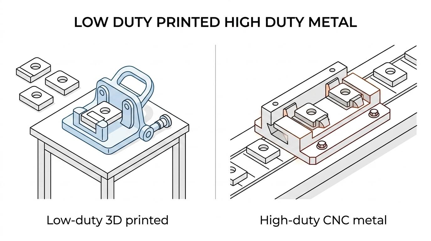
Additive tooling is faster and more shape-flexible, while CNC aluminium and steel are stronger and more durable. The right comparison is not printed versus machined. It is speed and adaptability versus maximum life and stiffness.
TechCAD notes that CAD compatibility and clean data exchange are often what actually enable fast redesign cycles across suppliers, which is why change speed can rival raw material strength in day‑to‑day performance.
Additive tooling usually wins on lead time, geometry freedom, weight and customisation. That can reduce operator fatigue and make awkward fixtures easier to handle. NIST notes that AM can also avoid costs tied to inventory, warehousing, obsolescence and maintaining older tools.
CNC-machined aluminium wins when you need a stable, accurate fixture with reliable wear performance. Steel wins when temperatures, cycle counts or surface damage risk push polymer tooling too far. A common mistake is treating these as mutually exclusive categories. Many of the best industrial tools are hybrids: printed structures with metal dowels, threaded inserts and hardened contact faces.
“PartMade3D provides production parts, tooling and prototypes for automotive, aerospace, defence, medical, robotics and mining applications.”
Which materials suit industrial tooling best, from PA12-CF to TPU?
PA12-CF, ASA, TPU and metal each suit different tooling loads and environments. The material should match the failure mode before it matches the budget.
For industrial polymer tooling, material choice is usually about stiffness, heat, wear, electrical behaviour and surface interaction with the part. Stronger is not always better. In many tools, controlled flexibility protects the part and improves repeatability.
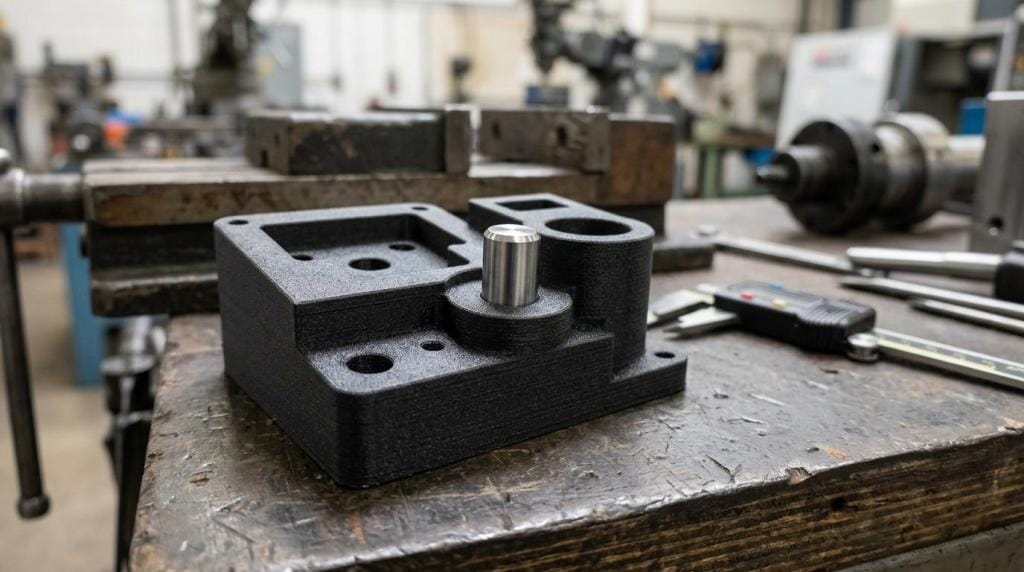
- PA12-CF: A strong choice for stiff, lightweight fixtures and brackets where low warp, dimensional stability and heat resistance matter. PartMade3D lists 75 MPa tensile strength and 131 °C heat deflection temperature at 0.45 MPa.
- ASA: Better for visual aids, covers and tooling used around UV exposure or outdoor conditions where weathering matters.
- TPU: Useful for compliant grippers, protective jaws and nests that must avoid marring delicate components.
- ESD-safe polymers: Worth considering for electronics handling, static-sensitive assemblies and test tooling.
- Aluminium or steel: The better option for high-wear datums, sharp edges, sustained thermal load and long production campaigns.
One pro tip is to choose material by contact zone, not only by overall part. A rigid body with soft pads or metal inserts often beats a single-material tool.
How do you select a 3D printing material for industrial tooling step by step?
Material selection should follow load, environment and interface sequence. PA12-CF and TPU solve very different problems, even when the tool geometry looks similar.
Start with the load case. Is the tool bending, compressing, rubbing or just locating? If the main issue is stiffness, short-span support and dimensional control, PA12-CF is usually a better starting point than a flexible polymer.
Next check the environment. Heat, oils, cleaning agents and moisture exposure can matter more than headline strength. If the tool sits near warm equipment, pay attention to heat deflection temperature. If it touches painted or polished parts, surface compliance can outrank stiffness.
Finish with interface details and service strategy. If the datum face wears first, design it as a replaceable insert. If operators will drop the tool, toughness and repairability matter. The best printed tooling material is the one that survives the real line behaviour, not the lab ideal.
How do you validate an industrial tool before full deployment?
Validation should be staged, measured and documented. A fixture in Brisbane or Perth should prove repeatability on the line before anyone treats it as production-ready.
First, inspect the tool itself. Check critical dimensions, flatness, hole positions, insert fit and any threaded features. For printed tooling, also inspect warpage at datum faces and verify that the build orientation has not compromised the main load path.
Second, run a controlled pilot. Use the real part, the real operators and the real cycle sequence. Record load feel, ease of use, clamp repeatability, part seating and any witness marks. If the tool fails only after repeated use, a single trial part will miss the actual problem.
Third, lock the result into a basic control plan. Define acceptable wear, cleaning method, storage conditions and replacement triggers. A common misconception is that tooling validation ends with first-pass success. Good SOPs treat the first pass as the start of monitoring, not the end.
What design rules improve jig, fixture and gauge performance?
Industrial tooling performs better when datum control, wear protection and ergonomics are designed in early. PA12-CF and aluminium both benefit from the same discipline.
A strong fixture does not just hold a part. It locates the part in a predictable way, gives the operator obvious access and protects the highest-wear points. Printed tooling adds another rule: do not waste material on zones that do not carry load.
Useful design rules include:
- Large radii at high-stress corners
- Short load paths between clamp and datum
- Replaceable contact pads
- Metal inserts for threads and bushes
- Reliefs for debris, swarf or powder
- Clear operator handholds and orientation cues
If the tool needs tight accuracy at a few interfaces, machine or post-process only those interfaces. That is often faster and cheaper than machining the entire tool from metal.
When should you avoid printed tooling and use conventional tooling instead?
Printed tooling should be avoided for cutting edges, sustained high heat and very high wear. Tool steel, hardened inserts and machined aluminium are safer when the duty cycle is unforgiving.
Move away from printed tooling if the tool must hold micron-level accuracy under heavy clamp load, resist constant abrasion, survive continuous hot processes, or meet regulatory traceability that demands established metal tooling routes. The same applies when failure would create an unacceptable safety risk.
That does not mean additive is out. It often means hybrid is better. If the fixture body is complex but only the locators wear, keep the printed structure and upgrade the wear surfaces. If the tool is large and awkward, a printed prototype can still validate geometry before cutting aluminium or steel. The best industrial tooling plan often uses additive first and conventional tooling where service life proves it is needed.